KYL-500L

PRODUCT > RF MODULES > KYL-500L

KYL-500L

Features


1.Ultra-low power consumption, less than 25mA in receiving mode , less than 1uA in sleep mode .

2.  The battery can be as supply (such as lithium batteries).

3.  High sensitivity, high output power (up to 400mW or more at 3.6V)

4.  8 optional channels, optional communication rate.

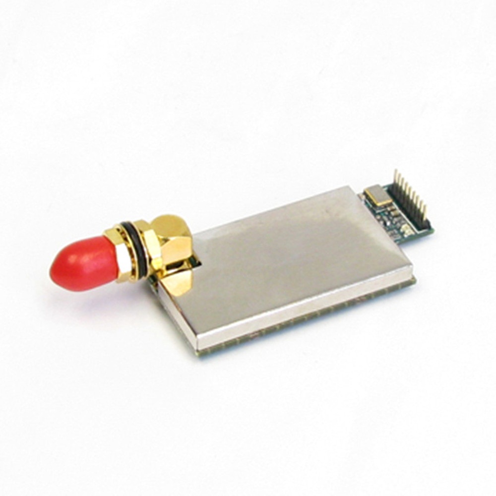
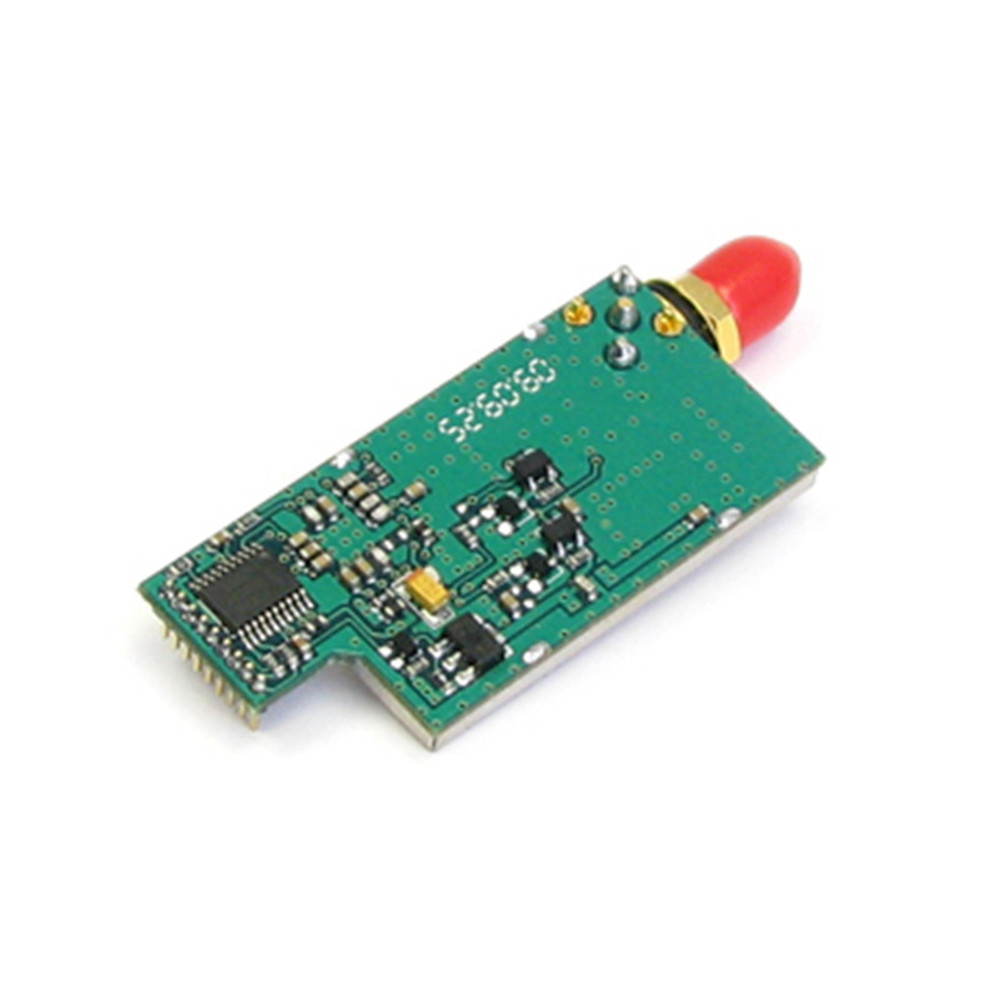
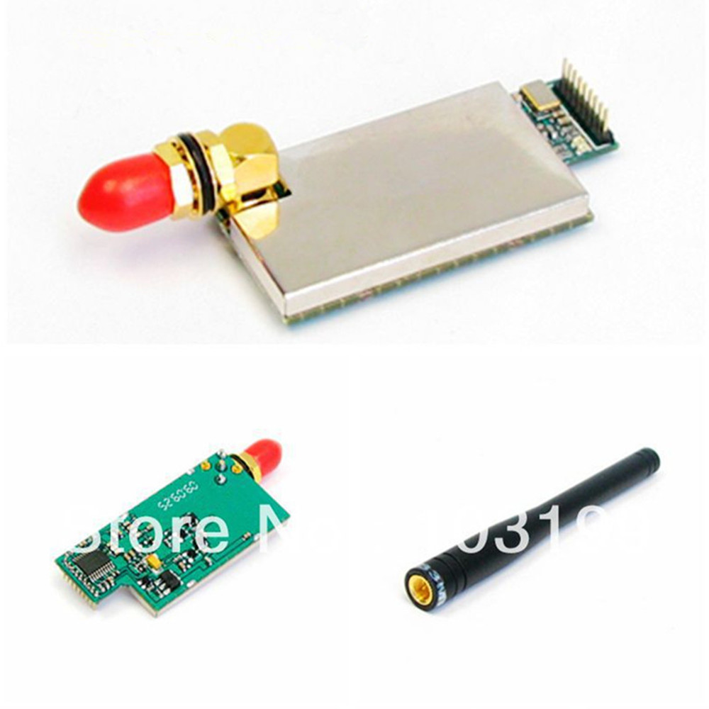
5. Small size, easy installation, easy to embed user equipment.

6. The whole module has good shielding performance. When used in embedded, it can effectively prevent mutual interference between devices.


Application


Wireless call system, wireless queuing machine, medical vessel;

Wireless POS, PDA;

Wireless data transmission, automated data acquisition system;

Wireless LED display, answering device, etc., intelligent transportation;


Technical specification 
                                                                   
                                                            KYL-500L Parameters
FeaturesRangeRemark
Power supply D.C.3.3v3.3-5v
Frequency400Mhz420/450Mhz
Output power400mW--
Transmitting Current 

<300mA

--
Receiving Current<25mA--
Sleeping Current

<1uA

Specify when place order
Receiver sensitivity-120dBm1200bps
-118dBm9600bps
Transmission distance2Km Line-of-sight, the height of antenna 1.5m
Dimension49mm*23mm*10mmWithout Antenna connector

Table: Transmission distance 、Receiver sensitivity and baud rate
 

Baud rateBps

Receiver sensitivity

Transmission distance(Line-of-sight)

1200

-120dbm

2500m

2400

-118dbm

2100m

4800

-116dbm

1600m

9600

-113dbm

1200m

19200

-110dbm

800m

 
 Pin Definitions

                                             KYL-500B Interface schematic


Interface name

Function description

Level

Remark

1

GND

Power Ground


2

VCC


Supply(DC)

3.3-4.2V


3


4

GND


5

TEST

Internal test


6

Reserved


TTL


7

Sleeping

TTL level

TTL

Low level active

8

RXD

Data receiving

TTL


9

TXD

 Data transmitting

TTL


 Table: Channel and RF Frequency

CH NO.FrequencyCH NO.FrequencyCH NO.FrequencyCH NO.Frequency
1429.0325MHZ2430.0325MHZ3431.0325MHZ4432.0325MHZ
5433.0325MHZ6434.0325MHZ7435.0325MHZ8436.0325MHZ


The Function-indicator light

1、The LED indicator light will glitter red and green for 0.5S once after switched on.
2、 The LED indicator light will glitter green continually while receiving data from air.
3、 The LED indicator light will glitter red continuously when transmitting data into air after receiving from COM.
4、 If the module enables the sleep function, LED indicator light is always dark. 

Timing Diagram

1、When Module A transmits data and module B receives data

 That is, the delay time that the terminal A (connected to the module A) sends data to the terminal B (connected to the B module) by wireless. Which be fixed to the time for transmitting 15 bytes. This time is related to the air baud rate, but not to the interface baud rate. details as follows:


 dd01.jpg
Table: Baud rate and delay time

Baud rate(Bps)

Delay time(ms)

19200

8

9600

15

4800

30

2400

60

1200

120

2、Module transceiver conversion time

 That is, the time for converting from the receive state to the transmit state, or from the transmit state to the receive state. During this time (100us), the module cannot receive air data.


dd02.jpg

How to use KYL series micro power wireless data module

Power supply:

    +3.3~6.0V DC,According to the needs of users, it can share the power with other devices, but please select a power supply with a better ripple factor.If conditional, 5V regulators can be used to supply power alone. It is recommended not to use the switching power supply. If you must use the switching power supply, please pay attention to the interference due to switching pulse.In addition, if there are other devices in the system equipment, it must be grounded reliably. Otherwise, it can be self-contained, but it must be completely separated from the city electricity. The maximum output current of the power supply should be more than 1.5 times the maximum operating current of the module.

Packaging accessories

1、Standard accessories

      1、1pc KYL-500L module。

      2、1pc antenna(about 10cm)


2、Selectable accessories

1、TTL interface programming cable。(for users to set parameters through RS232 interface of the computer)

    2、Power supply

    3、Selectable antenna。(Users can choose antenna if need)

    Pic.:Selectable accessories


1020L可选配件


Previous: KYL-324
Next: KYL-500S