
KYL-811
KYL-811

1 channel ON-OFF DI and DO transmitting timely. The 1 channel switching condition for the transmitting equipment can be output timely at the receiver equipment. That is the switching condition for the transmitting equipment is shut down, while the switching condition will be shut down at the receiver equipment; and the transmitting equipment is disconnect, while the receiver equipment will disconnect. All channels are independent.No program,no wires,users can remote control switching.This product is widely-used in Industrial controller,wireless monitoring,waterworks automation and other projects.
一、KYL-801L Application diagram
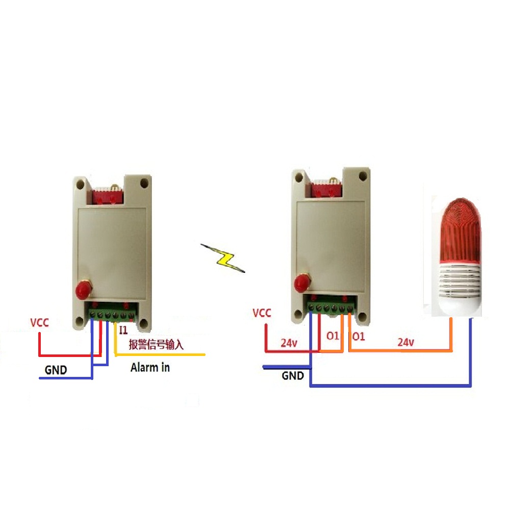
Pic. 1:Working diagrams for correspond I/O information

Wireless water pump automatic control
Wireless sound and light alarm lights
Industrial remote control, industrial site monitoring
Wireless car control
Water plant automation
Traffic Automation Control
Environmental Monitoring System
Oil pipeline monitoring system
| Features | Range | Typical value | Remark |
| Power supply D.C. | 12-30V | 24V | Output Current<500mA |
| Transmission distance | 1-3 KM | - | Line-of-sight |
| Ourput No. | - | 1 output | - |
| Output type | - | Relay | Maximum load capacity DC 220V5A |
| Input No. | - | 1 input | - |
| Input type I | - | Dry Contact | - |
| Input type II | DC 0-24V | Low level<1V | Low level corresponds to closed |
| High Level>3V | High level corresponding to disconnected | ||
| Transmitting Current | - | <300mA | - |
| Receiving Current | - | <20mA | - |
| Dimension | - | 89mm*41mm*32mm | - |
Remarks: The input type has been specified according to the customer's requirements. So can not be changed after shipment.
1、 DIP1-4:Channels choosing


*Users generally use the inputting change sending mode, DIP7-ON;
*To avoid more than two remote control systems working at the same time in one remote control range, the module for different system should choose different channel (working frequency);
*In timing mode, one must be the master and the other is the slave
*It should be effect by re-power on the module after changing the DIP position.
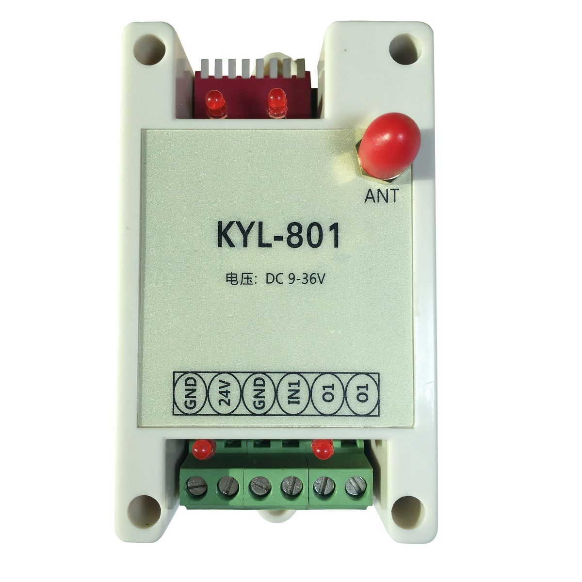
| Pin no. | Color | Pin Definition | Remark |
| 1 | Black | GND | Grounding of power supply |
| 2 | Red | 12V | DC:12-30V |
| 3 | Yellow | OUT1(O1) | First channel relay dry contact output |
| 4 | White | OUT1(O1) | |
| 5 | Blue | IN1(I1) | First group ON-OFF input |
| 6 | Orange | GND |
1、install the antenna to the module.
2, in accordance with the use of demand, according to the above instructions set the DIP switch, connect the corresponding switch input, switch output device.
3, connect the power (12-30V), turn on the power switch, the power requirements of the output current needs reach more than 500mA.
4, At this point, the input of module can control the output of another module .
5, the module is two-way transmission, that is, a module can as an input ,at the same time, can also be used as a controlled output, and vice versa.
6, Within the same remote control distance range if user using more than two sets of remote control system, one should use a different operating frequency to avoid mutual interference.
Working Mode
1、Triger mode
When ON-OFF input status changed,it will triger I/O Module to send the local status information. This mode has fast speed,can be in real time.Only when input status changed,then will send the signal,the energy consumption will be low.
2、Timer mode
At this mode, there should be one master and one slave module. The master will
synchronize with the slave every 1s, means the master will transmits its condition to slave every 1S and the slave will feedback its condition to master every 1S. If the time master cannot synchronize with slave reaches at 3S, all contacts will disconnect. They connects until the master is synchronizing with slave again. There will be 1s transmission delay at this mode.
3、Collecting mode
At collecting mode, DIP8(transmitting mode), DIP7(master/slave mode) and DIP5(repeater/feedback mode) are all invalid. At this mode, module works as a Modbus slave, it can not transmit data actively. Master can be a PC connecting with a wireless data module or other data terminal. Data terminal sends Modbus RTU
command and requests slave feedback collection condition or control slave’s ON-OFF output. Slave’s ID can be 1 to 254.
4、Feedback/repeater mode
At feedback/repeater mode, receiver will retransmit the command it received and make it reach longer distance. It functions as a repeater. The transmitter will output related ON-OFF condition on its output COM after receiving retransmitted command, meanwhile, the output indicator will be ON/OFF. Its output condition will be the same with its input condition. If receiver didn’t receive the command, it will not retransmit, feedback will fail. Master’s output condition will be not the same with its input. This function can monitor receiver’s output results.
KYL-811 Other application
KYL-811 can work with same series I/O Module: KYL-813,to reach the function of centralized control,and centralized output (please indicate to sales when you set the purchase order).Please look the below diagram as example:
Ordering information
Standard product
| Module Name | Application |
| KYL-811U | Bi-directional, 2pcs of this RF modules will help you do wireless communication., no program, plastic housing, communication distance 600m-1km (Line of Sight) based on power 100MW |
| KYL-811L | Bi-directional, 2pcs of this RF modules will help you do wireless communication., no program, plastic housing, communication distance 2-3km (Line of Sight) based on power 800MW |
| KYL-811H | Bi-directional, 2pcs of this RF modules will help you do wireless communication., no program, plastic housing, communication distance 7-10km (Line of Sight) based on power 5W |
| KYL-811P | Bi-directional, 2pcs of this RF modules will help you do wireless communication., no program, plastic housing, communication distance 8-12km (Line of Sight) based on power 2-10W |
| KYL-811+668 | Bi-directional, 2pcs of this RF modules will help you do wireless communication., no program, plastic housing, communication distance 20km (Line of Sight) based on power 25W |
1、Standard accessories
1、1pc KYL-811 module。
2、1pc antenna
Pic.:Standard accessories

2、Selectable accessories
1、Selectable antenna。(Users can choose antenna if need)
Pic.:Selectable accessories