
KYL-813-LORA

KYL-813-LORA

2-way I/O Module can achieve wireless transmission in real time, the relay output of receiver module is connceting with ON-OFF input of the transmitter relay output. In other words, when the input of the transmitter switch on, the corespond relay output will be on at the same time.when the input of the transmitter switch off,the corespond relay output will be off at the same time.All channels are independent.No program,no wires,users can remote control switching.This product is widely-used in Industrial controller,wireless monitoring,waterworks automation and other projects. The wireless transmission uses LORA wireless modulation technology, which has a longer transmission distance, stronger anti-interference ability and multi-path fading resistance, and is more suitable for complex environments with dense buildings and large electronic interference.
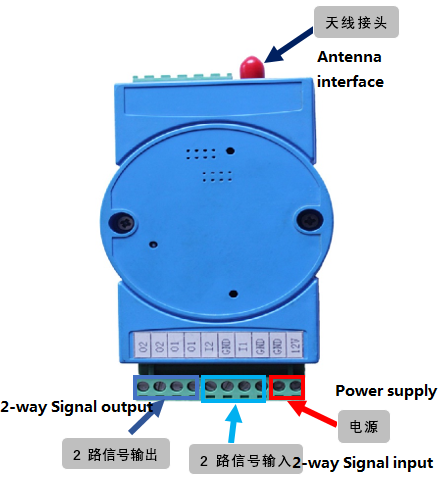
一、KYL-813-LORA Hardware Terminal Diagram
二、KYL-813 Connection diagram

Wireless water pump automatic control
Wireless sound and light alarm lights
Industrial remote control, industrial site monitoring
Wireless car control
Water plant automation
Traffic Automation Control
Environmental Monitoring System
Oil pipeline monitoring system
| Features | Range | Typical value | Remark |
| Power supply D.C. | 9-15V | 12V | Output current≥500mA |
| Transmission distance | 5-7 KM | - | Line-of-sight |
| Ourput No. | - | 2 output | - |
| Output type | - | Relay | Maximum load capacity DC 220V5A |
| Input No. | - | 2 input | - |
| Input type I | - | Dry Contact | - |
| Input type II | DC 0-24V | Low level<1V | Low level corresponds to closed |
| High Level>4.5V | High level corresponding to disconnected | ||
| Transmitting Current | - | <300mA | - |
| Receiving Current | - | <20mA | - |
| Dimension | - | 100mm*58mm*40mm | - |
Remarks: The input type has been specified according to the customer's requirements. So can not be changed after shipment.。
| Connection name | Pin No. | Definition | Remarks |
| 1 | VCC | DC 12V (9-15V) | |
| 2 | GND | Grounding of power supply | |
| 3 | GND | ||
| 4 | IN1(I1) | First group ON-OFF input | |
| 5 | GND | ||
| 6 | IN2(I2) | Second group ON-OFF input | |
| 7 | OUT1A(O1) | The first channel of relay output A contacts | When the relay shutting,A and Bconnected |
| 8 | OUT1B(O1) | The first channel of relay output B contacts | |
| 9 | OUT2A(O2) | The second channel of relay output A contacts | When the relay shutting,A and Bconnected |
| 10 | OUT2B(O2) | The second channel of relay output B contacts |
Using Method
1. Install the antenna to the module.
2. In accordance with the use of demand, according to the above instructions set the DIP switch, connect the corresponding switch input, switch output device.
3. Connect the power (12-30V), turn on the power switch, the power requirements of the output current needs reach more than 500mA.
4. At this point, the input of module can control the output of another module .
5. The module is two-way transmission, that is, a module can as an input, at the same time, can also be used as a controlled output, and vice versa.
6. Within the same remote control distance range if user using more than two sets of remote control system, one should use a different operating frequency to avoid mutual interference.
Working Mode
1. Triger mode
When ON-OFF input status changed, it will triger I/O Module to send the local status information. This mode has fast speed, can be in real time. Only when input status changed, then will send the signal, the energy consumption will be low.
2. Timer mode
At this mode, there should be one master and one slave module. The master will synchronize with the slave every 1s, means the master will transmits its condition to slave every 1S and the slave will feedback its condition to master every 1S. If the time master cannot synchronize with slave reaches at 3S, all contacts will disconnect. They connects until the master is synchronizing with slave again. There will be 1s transmission delay at this mode.
3. Collecting mode
At collecting mode, DIP8(transmitting mode), DIP7(master/slave mode) and DIP5(repeater/feedback mode) are all invalid. At this mode, module works as a Modbus slave, it can not transmit data actively. Master can be a PC connecting with a wireless data module or other data terminal. Data terminal sends Modbus RTU command and requests slave feedback collection condition or control slave's ON-OFF output. Slave's ID can be 1 to 254.

Acquisition Mode Networking Diagram
4. Feedback/repeater mode
At feedback/repeater mode, receiver will retransmit the command it received and make it reach longer distance. It functions as a repeater. The transmitter will output related ON-OFF condition on its output COM after receiving retransmitted command, meanwhile, the output indicator will be ON/OFF. Its output condition will be the same with its input condition. If receiver didn't receive the command, it will not retransmit, feedback will fail. Master's output condition will be not the same with its input. This function can monitor receiver's output
results. If the user is not familiar with the product and is unfamiliar with the method of use, all code switches should be pull to the ON position to test.
KYL-813-LORA Other application
In addition to the one-to-one switch transmission and the acquisition and control of one master multi-slave switch in acquisition mode, KYL-803-LORA can also be used in conjunction with other switch transmission modules of our company to realize centralized control and centralized output. Note that these features need to be specified before purchase). The illustration is as follows:
Ordering information
Standard products
| Module Name | Remark |
| KYL-803U | Bi-directional, 2pcs of this RF modules will help you do wireless communication., no program, plastic housing, communication distance 600m-1km (Line of Sight) based on power 100MW |
| KYL-803 | Bi-directional, 2pcs of this RF modules will help you do wireless communication., no program, plastic housing, communication distance 2km-3km (Line of Sight) based on power 800MW |
| KYL-803H | Bi-directional, 2pcs of this RF modules will help you do wireless communication., no program, plastic housing, communication distance 7km-10km (Line of Sight) based on power 5W |
| KYL-803P | Bi-directional, 2pcs of this RF modules will help you do wireless communication., no program, plastic housing, communication distance 8km-10km (Line of Sight) based on power 2W-10W |
| KYL-803+668 | Bi-directional, 2pcs of this RF modules will help you do wireless communication., no program, plastic housing, communication distance 20km (Line of Sight) based on power 25W |
1. Standard accessories.
a. 1pc KYL-813 module
b. 1pc small magnetic antenna
Pic.:Standard accessories

2. Selectable accessories
Selectable antenna. (Same gain)
Pic.:Selectable accessories

In addition to the above antennas, we also have high gain antenna such as:
1. Yagi antenna
2. Big magnetic antenna
3. Clip antenna