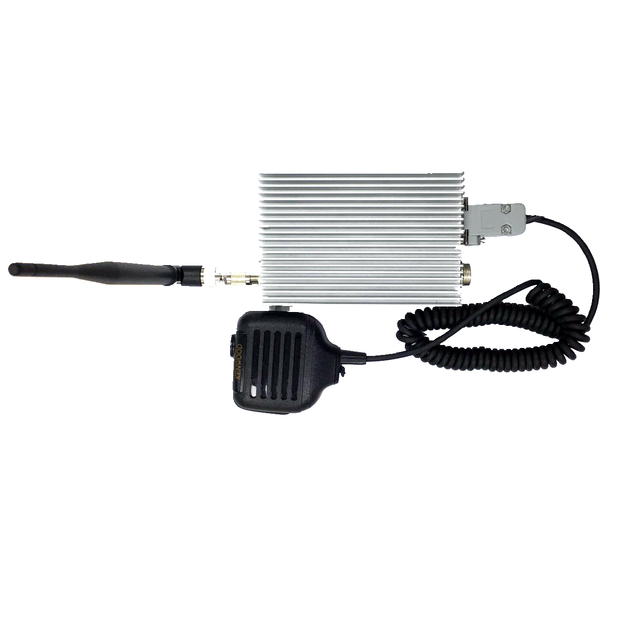
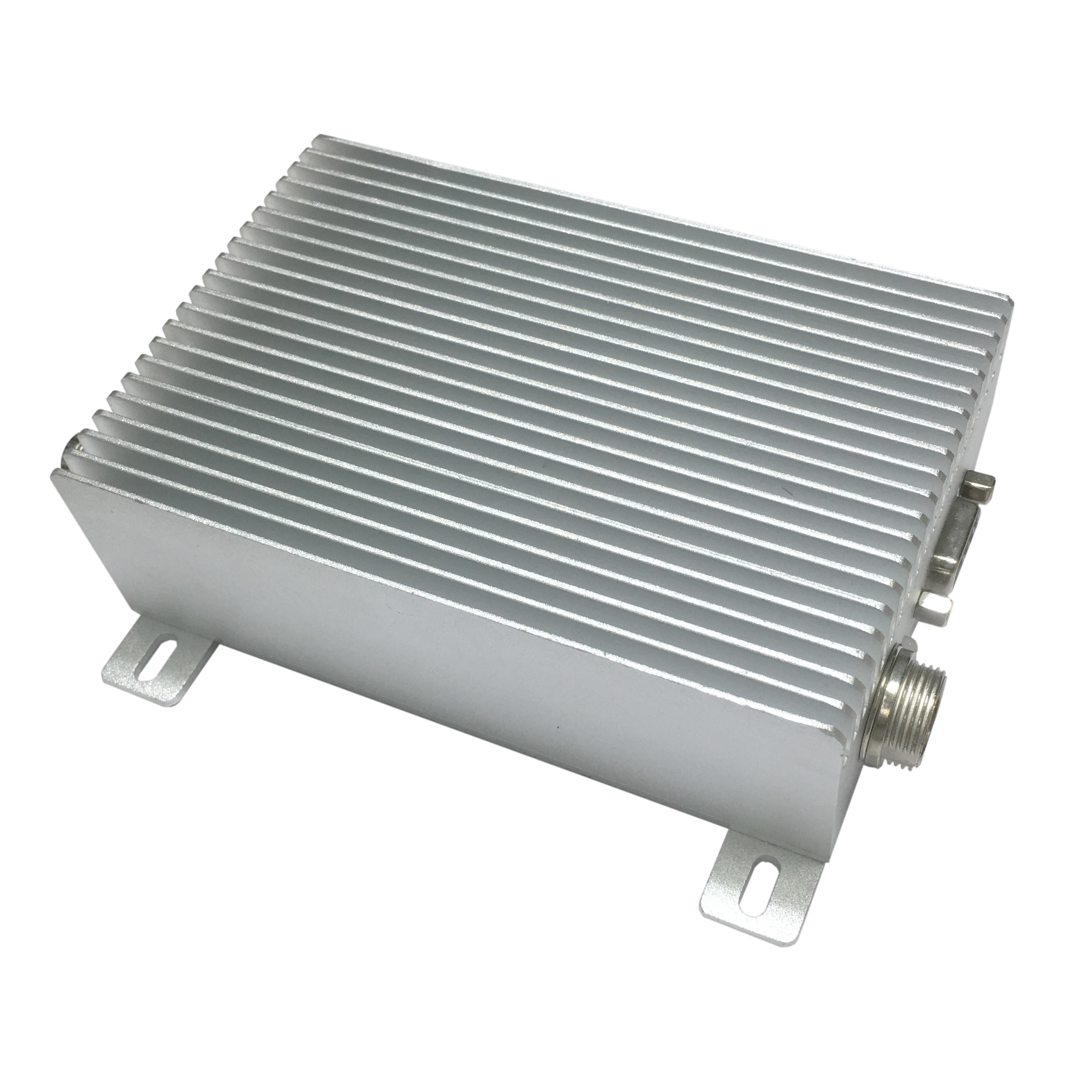
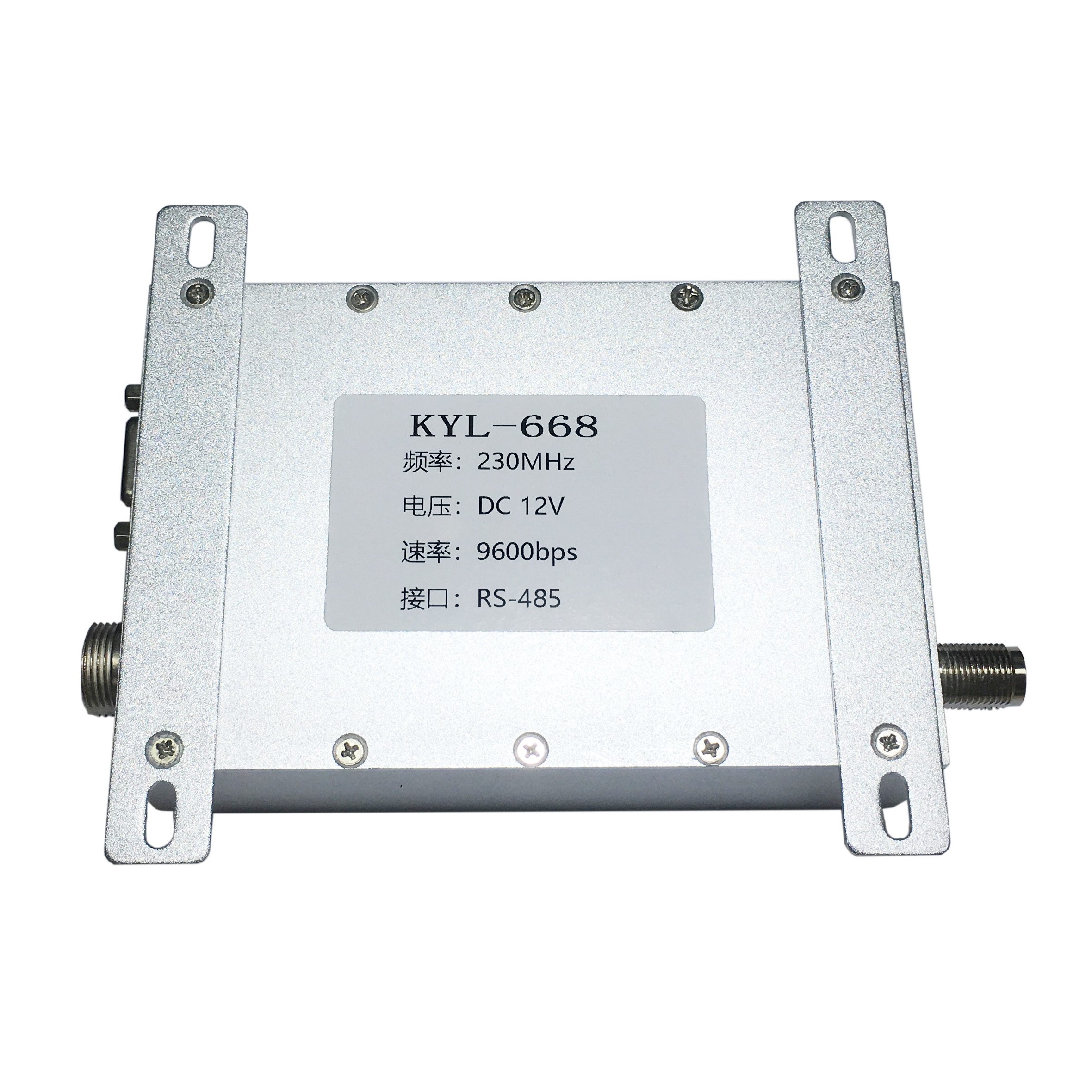
KYL-668H
1. Transmission power
Using imported power amplifier module inside , transmission power 25W (adjustable ), Dimension 108mm × 128mm × 28mm.
2. ISM band working frequency, no need to apply carrier frequency, such as 150/230/450MHz etc, up to 256 channels.
3. High anti-interference ability and low bit error rate
Based on the MSK modulation method, an efficient communication protocol is used. When the channel error rate is 10-2, the actual bit error rate can be 10-5 ~ 10-6.
4. It can transmit voice or data signals for use as a wireless car intercom station.
5. Transparent data transmission.
Provides a transparent data interface that can adapt to any standard or non-standard user protocol. Automatically filter out noise signals and false data generated in the air. Transceiver conversion time: <50ms
6. Multi-Baud rate.
Air Baud rate: 1200bps, 2400bps , Interface baud rate 1200,2400,4800,9600,19200, can be set by users .
7. Can use the computer to set the transmission frequency, change the channel, and determine the working mode.
8. Can be as Receiver or transmitter, half-duplex communication, switching quickly.
9. Double phase-locked loop, dual VCO structure, high stability.
10. RS-232, RS-485, TTL Multiple standard interfaces are optional and can be directly connected to user equipment.
11. The interface uses standard TTL, RS-232 (or RS-485) levels and can be directly connected to a microcontroller or personal computer
Ships, urban transport, taxi intercom systems, wireless call systems
Industrial automation control, power dispatch, railway signal acquisition
Water conservancy project monitoring, hydrology hydrological monitoring, meteorological data transmission, environmental protection monitoring equipment, oil production and transportation monitoring
Forestry protection facilities, wireless beacons, river navigation, geological exploration, GPS positioning information, military training, public security alarm, remote telemetry and other automated control areas
Picture transmission wireless intercom system
| Features | Range | Remark |
| Power supply D.C. | 12v | -- |
| Frequency | 150Mhz | 230/470Mhz |
| Output power | 25W | -- |
| Transmitting Current | <6A | |
| Receiving Current | <70mA | |
| Sleeping Current | <60mA | Specify when place order |
| Receiver sensitivity | ||
| Transmission distance | 20Km | Line-of-sight, the height of antenna 1.5m |
| Dimension | 108mm×128mm×28mm | Without Antenna connector |
KYL-668H Pin Definitions
| Interface name | Function description | Level | Remark |
1 | GND | Ground |
|
|
2 | A(TXD) | RS-485 A OR TXD of RS-232/TTL |
|
|
3 | B(RXD) | RS-485 B OR RXD of RS-232/TTL |
|
|
4 | NC |
| ||
5 | DGND | Signal Ground |
|
|
6 | PTT | Voice transmission control |
|
|
7 | MIC IN | Microphone input |
| |
8 | SPEAKER OUT | Speaker output(0.5W 8Ω) |
| - |
9 | TEST | Internal test |
|
|
Basic parameters
● Frequency:150/230/450 MHz
● Frequency tolerance:±2.5ppm
● Channel spacing:25KHz
● Antenna impedance:50Ω
● Ambient temperature:-35℃~+75℃
● Modulation:MSK
● Baud rate:1200/2400bps
Receive parameters
● Available sensitivity:≤0.25uV
● Singal to noise ratio: ≤50dB
● Adjacent channel selectivity: ≥70dB
● Intermodulation immunity: ≥70dB
● Spurious response immunity:≥70dB
Transmitting parameters
● Transmitting output power: 5-25W
● Modulation distortion: ≤3%
● Remaining FM:≤-48dB
● Data frequency offset: ≤4KHz
● Adjacent channel power ratio: ≤-70dB
● Spurious frequency components:≤-36dBm
Supply power
● Voltage: 12V (±10%)
● Waiting current: ≤ 60mA (Needs low current, can be customized)
● Transmitting Current: ≤ 6 A (Transmitting output power 25W)
1、Power Supply:
Due to the big power of radio station, the general transmission power is 25W, the power supply capacity meets 12V 8A. Please select a power supply with a better ripple factor and strong anti-interference ability. If The switching power supply is used. Please pay attention to keeping the antenna away from the power supply as much as possible because the antenna may affect the normal operation of the switching power supply. When radio station transmission fails, check if the power supply voltage is tampered by the antenna, it is one of the troubleshooting methods.
2、Antenna:
The antenna should be selected according to the frequency band used by the radio station. In long-distance transmission, directional antennas or high-gain antennas should be used, which should be set as high as possible.The impedance of antennas and its cable should match the one of interface of the module (50 Omega;). If the antenna impedance does not match, the module efficiency will be very low, the power consumption will increase, and it will be easily damaged for radio station. Antenna erection should be paid attention to lightning protection and antenna directionality, and grounding should be good.
3 、Cable
The feeder line is a coaxial cable, which connects between the radio and the antenna. Selecting feeder line should pay attention to the following indicators:
Impedance: 50 Omega; (There are two types of 75 Omega; and 50 Omega, please note the difference)
Attenuation: Attenuation Decibels (DB) per meter feeder line. The smaller, the better.
Wire diameter: The thicker the feeder line diameter and the thicker the shield, the smaller the attenuation of the feeder.
Feeder line connector: The two ends of the feeder line must match the ones of the antenna and radio station. The connector's impedance is also 50 Omega; and it must be securely connected. When installing the feeder line,be careful not too tightly. Take a loop around the feeder line when enter the room,which prevents rainwater from entering the radio station. In Dorayan areas or when the antenna is installed at a high level, an arrester must be installed.
4 、Cooling
When the radio station is transmitting for a long time, heat generated must be emitted in a timely manner. If can not, it may easily cause the wireless transmission to work abnormally.
1、Standard accessories
1、1pc KYL-668H module。
2、Power supply cable


